TECH TIPS INTRO
At DeWeyl Tool, one of our goals is to provide our customers with up-to-date technical information for the use and maintenance of our tools.
After reviewing the Tech Tips within this section, if you have a specific question that you would like to ask us, please feel free to send us an email and we’ll be happy to get you the additional information you need.
CONCAVE BONDING WEDGES
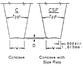
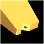
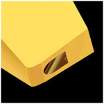
The Concave Bonding Wedge is offered for customers using small diameter aluminum bonding wire. Small diameter wire is generally viewed as wire that runs between .001″ dia. Up to .002″. Aluminum wire (small) is offered in the following diameters. .001″, .00125″, .0015″ and .002″. Anything over .002″ diameter is usually considered a large wire application.
Additionally, the Concave Bonding Wedge is used for bonding aluminum wire, because the arch at the back of the bond foot offers additional material thickness, and thus strength for the wire. Aluminum wire is very brittle and needs this additional thickness to minimize the chance that the aluminum wire could easily break at the heel of the bond foot.
CONCAVE WITH SIDE FLATS
This tool is identical to the “Concave” tool and is used for the same reasons. However, occasionally we will have a customer using gold wire with the concave style tip. As a result, the outside edges of the wedge may contact the bonding surface when the bonding wire is deformed. To prevent the tool contact on the edges, we offer side flats to give extra clearance, thus eliminating the tool contact to the bonding surface.
THE BONDING TOOL RADIUS
Front Radius | Back Radius
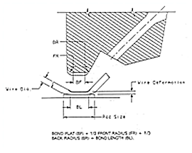
The front radius and back radius of the bonding tool can sometimes seem like something rather insignificant. But actually, the proper selection of radii, especially the back radius, is very important to the strength of the wire bond system. The FR and BR need to be modified based on the type of wire being bonding, i.e. gold or aluminum. You must also consider the wire size when deciding the size of the radius. Generally speaking, gold wire will use a smaller back radius to help cut the wire cleanly. Aluminum wire is harder and more brittle. It needs to have a smoother radius to prevent cracking of the wire.
FRONT RADIUS
The front radius of the bond tool needs consideration on the second bond. The first bond does not matter much with regard to the front radius. The front radius’ main job is to offer a smooth and gentle transition between the bond flat and the wire diameter at the second bond contact. The most common choices for the front radius on .001″ diameter wire is FR= .001″ for both aluminum and gold wire.
BACK RADIUS
The back radius is the critical radius. If this is selected incorrectly an aluminum wire may break very easily or a gold wire may not terminate properly. The most common choices for the back radius on .001″ diameter wire is BR= .001″ for aluminum wire and BR= .0005″ for gold wire.
THE WIRE FEED HOLE
Wire Feed Hole | Looping Performance | Feed Hole Diameter | Feed Hole Problems | Feed Hole Wirelock | Feed Hole Length
THE WIRE FEED HOLE IS IMPORTANT
The feed hole on the bonding wedge is likely the most critical aspect of the wedge configuration. The feed hole has the responsibility of guiding the wire accurately to the center of the bond foot. The feed hole’s most significant contribution is how it defines the looping performance for our customers.
LOOPING PERFORMANCE
What do we mean by looping performance? Our customers use our product to attach wires between two points. This wire needs to have an arc shape in order to prevent shorting on other circuitry within the electronic device. If a wire is laid flat, it would sag down and touch other electrical points in the customer’s product. If the wire is shaped into an arc similar to the shape of a bridge spanning a stream, then the wire is stronger, just like the bridge is stronger. This wire shape is what we call the loop profile. The loop profile can be very low or it can very high for a variety of different reasons. The loop profile will be dictated by the length of the wire, the diameter of the wire and the height difference between the first and second bond. Our customers have to consider all these factors when deciding which wedge to utilize.
FEED HOLE DIAMETER
There is a very simple guideline to start with when selecting the diameter of the feed hole. Generally speaking, the feed hole diameter will be twice the diameter of the bonding wire. A .001″ diameter wire will use a .002″ diameter hole. Customers deviate from this general guideline for a variety of reasons.
FEED HOLE PROBLEMS
The feed hole plays such a critical role that it can also be the cause of many performance problems. These problems can be very difficult for our customers to resolve quickly because the symptoms can be caused from several different sources. These problems include poor wire feeding, poor looping, wire damage, poor wire termination and difficulty threading the wire. This is why accuracy on the feed hole diameter, the feed hole length, and the funnel depth are extremely critical.
FEED HOLE WIRELOCK
The feed hole gains control over the wire by producing “wire lock.” Wire lock is when the wire cannot slide through the feed hole. The wire is thus “locked” inside the feed hole. Wire lock takes place when the angle of the wire moves significantly away from the angle of the feed hole. In other words, the wire angle and the hole angle need to be at the same angle in order for the wire to freely pass through the feed hole. If the angles of the wire and hole are not the same, then there will be friction on the wire. The greater the angle differential the greater the friction. Eventually the friction is high enough to achieve wire lock. Then the tool is in control of the wire and in control of the loop profile. A couple of feed hole aspects can cause significant wire lock problems. The two primary aspects would be the hole diameter in relationship to the wire diameter, as well as the feed hole length.
FEED HOLE LENGTH
One of the other factors that contributes to wire lock performance is the length of the feed hole. The length of the feed hole is altered when the depth of the funnel is altered or if the “T” dimension of the tool is modified.
THERMOCOMPRESSION BONDING
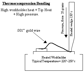
The microwave industry primarily uses a method called “thermocompression bonding” on gold wire.
Thermocompression bonding is used for bonding gold wire with heat, pressure and time. No ultrasonic energy is applied to the bond wire. This bonding process requires elevated temperatures during the bonding process when compared to “thermosonic bonding”.
The heat is supplied by a heated workholder, which holds the part being bonded. The bonding wedge is usually heated as well. The bonding machine supplies the pressure as it pushes down the wedge onto the wire. The time or duration is how long the bonding wedge sits on the wire.
THERMOSONIC BONDING
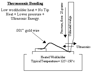
Thermosonic bonding is used for bonding gold wire with less heat, less pressure and less time, when compared to the thermocompression technique. This bonding process allows reduced temperatures during the bonding process.
The addition of ultrasonic energy is what allows all of the reductions in heat and pressure. The lower heat is still supplied by a heated workholder, which holds the part being bonded. The bonding wedge is usually unheated. The bonding machine supplies the lower pressure as it pushes down the wedge onto the wire. The time or duration is how long the bonding wedge sits on the wire and this time requirement is typically reduced as well.
The ultrasonic energy results from a mechanical vibration of the wedge at a standard frequency of 63khz. New high frequency systems offer frequencies of 110-120Khz. The ultrasonic vibration of the wedge is what allows all the reduction in forces and temperatures, and scrubs the bonding wire into the metal interface.
CLEANING PROCESS FOR ALUMINUM WIRE BONDING TOOLS
MATERIALS REQUIRED
- Tool Tray
- Sodium Hydroxide
- (3) 400 ml glass beakers.
- Ultrasonic Cleaner
- Distilled water
- Isopropyl alcohol
- Dry compressed air
Step 1 | Step 2 | Step 3 | Step 4 | Note
STEP 1
Load all tools in tool tray with the point of the tool up. Do not place tools tip down in tray tip or tool damage will occur. Mix cleaning solution using water and sodium hydroxide. Mix (5) five parts water to (1) one part sodium hydroxide.
STEP 2
Place tool tray in 400ml beaker with enough Sodium Hydroxide cleaning solution to cover all tools completely. Place the beaker into the ultrasonic cleaner for approximately (3) three to (5) five minutes.
STEP 3
Transfer tool tray from cleaning solution beaker to 400ml beaker of hot water. Place beaker in ultrasonic cleaner for (3) three to (5) five minutes. Repeat this procedure with fresh hot water.
STEP 4
Complete the cleaning sequence with an alcohol rinse. Submerge the tool tray (2) two or (3) times in the alcohol solution and then blow-dry with clean dry air.
Warning: Do not use compressed air contaminated with moisture or oil.
NOTE
It’s important to insure the tools are properly secured during the ultrasonic cleaning process. Damage will occur if the tools are not held properly during the ultrasonic cleaning.
Tool trays are available from DeWeyl Tool and safely hold 60 tools per tray.
WEDGE TIP STYLES
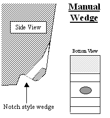
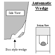
Notch Style Wedge | Box Style Wedge
The DeWeyl product catalog offers a significant variety of tools. The general difference between “Automatic” bonding wedges and “Manual” bonding wedges hinges on the difference between “notch” and “box” style wedges.
THE NOTCH STYLE WEDGE
We make several variations of the notch style tool. The notch style wedge is designed for use on manual wire bonders. The notch style wedge can be modified with more aggression than the box style.
For example, we can offer a narrower “W” dimension on a notch style because the walls of the box are missing from a notch style tool. Our “CS” series is the best choice for manual wire bonders and is especially useful for our microwave technology customers.
Why is the notch style a poor choice for automatic wire bonding equipment? If you look closely at the sketch of the notch tool you will see how the wire is free to move side to side once it exits the feed through hole. It is this characteristic that prevents the notch tool from being selected for automatic bonding applications. When a manual bonding operator looks through the microscope to place the wire bond he/she will target the wire to the bond pad. Thus, if the wire shifts side to side it does not pose any significant problem with regards to placement accuracy.
However, automatic wire bonders cannot see when the wire shifts from side to side. The auto bonder can only assume knowledge of the center of the wedge and thus attempt to place that wedge center on the center of the bonding pad. Thus, excellent wire centering is needed when operating an automatic wire bonder.
Notch style wedges: A, AS, CS & KS
WIRE TERMINATION METHODS
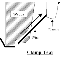
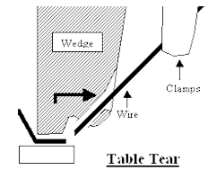
Clamp Tear | Table Tear
There are two basic methods that wire bonding equipment use to terminate the wire bond. The first is called clamp tear and the second is called table tear.
CLAMP TEAR
Just like it sounds, the wire bonding machine uses a set of clamp blades to clamp on to the wire immediately after the last wire bond contact is made and the clamps actually move back and pull on the wire with enough force to break the wire. This wire clamp movement must be done while the bonding wedge is in contact with the wire. The tool is pressing down on the wire while the clamps are pulling on the wire.
This sequence is very important. If the wedge is not holding the pressure down on the wire, the clamp pull force would likely lift up the already bonded wire connection. How does the wire know where to break? The wire will break at its weakest point. Where is that weakest point? If we assume that the correct bonding wedge is used, the weakest location will be at the back radius of the tool. This semi-sharp portion of the tool is designed to weaken the wire strength and allow for the wire to break at a predictable location. Many manual machines and a some automatic wire bonders use this technique to terminate the wire.
TABLE TEAR
This method still utilizes a set of clamp blades, however the clamps only clamp on the wire and do not have a motion to pull back on the wire. Instead, the wire bonding machine lifts up the wedge after the last bond is complete. This lift elevation is extremely low and is measured in just a few thousandths of an inch. After the tool lifts from the surface, the table moves such that the tool steps back and as a result breaks the wire.
Once again, how does it know where to break? The back of the bond foot has been weakened by the back radius design of our wedge. As a result of the semi-sharp back radius, the wire breaks at the desired location.
Since this wire termination method requires some motorized table movement, it is almost exclusively used on automatic wire bonders. The automatic equipment engineers like to use this method out of consideration for bonding speed. They can perform a table tear method faster than trying to perform a clamp tear sequence, because every fraction of a second is considered.
