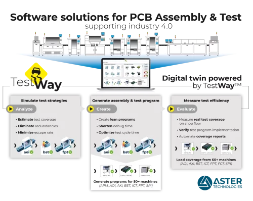
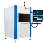
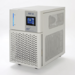
TestWay Express is a fully integrated solution that enables electronic manufacturers to optimize the design to test and the new product introduction flows. Test is essential for improving product quality by striving to detect and prevent all faults on a product. This maximizes the number of good products shipped to the customer. TestWay Express analyzes the number of defects detected at each stage in the test process and identifies any shortfall in test coverage and undetected defects. It allows the computation of the IPC metrics such as first pass yield (FPY), fall-of-rate or escape rate by importing the real time DPMO (Defect Per Million Opportunities) from the manufacturing process. The manufacturing test strategy is tuned to provide the optimal test coverage for identifying potential defects.
TestWay Express Design for test, Test Coverage & CADCAM Software
TestWay and TestWay Express are a proven solution, used by many PCBA designers and manufacturers worldwide, that provides a unique approach to analyze electrical testability requirements and estimate test coverage aligned to specific test strategies, at the earliest opportunity in the design cycle.
- Testability analysis from Schematic capture.
- Electrical rules checking automation.
- Test point optimization.
- Probe placement
- Integrated platform for coverage analysis.
- Provide yield estimation and test strategy cost modelling.
- Generate and optimize inspection and test program.
Quick Enquiry
Design for test, Test Coverage & CADCAM Software
- Design for Component
When the key components are selected, check the ROHS, reliability, defects per million opportunities (DPMO), boundary-scan description language (BSDL) file validation in order to guide component selection. - Electrical Design for Test
When the schematic sheets are defined, TestWay verifies the testability by conducting electrical rules checking that reflect the Design for Test (DfT) guide lines. These can include standard and customer’s specific checks relating to company requirements. - Test point saving
By simulating the test strategy prior to the layout phase, TestWay helps to minimize the need for physical accesses that are necessary to detect defects aligned to the defect universe. It helps to reduce test point access by 30% to 70%! - Select manufacturing strategy
TestWay estimates test coverage using theoretical models that reflect the capabilities for a wide range of test and inspection strategies, such as: Automated Placement Machines (APM); Automatic Optical Inspection (AOI); Automated X-ray Inspection (AXI); Boundary-Scan Test (BST); Flying-probe Test (FPT); In-Circuit Test (ICT) and Functional Test These models should be tuned to reflect the test and measurement capabilities of each individual target tester. - Test for Excellence
Once the test and inspection programs have been debugged and released, it is imperative to be able read the completed test program or test report and compare the coverage between the estimated and measured analysis. - Functional test coverage
Manage functional test as part of the overall test strategy, produce accurate coverage reports that assists the diagnosis of faulty boards in production and repair centers. - Test Probe Analyzer
When the layout is finalized, test probe placement should be optimized according to test strategy definitions. The probe access information can then be used for estimating the test coverage, modeling the cost and calculating the production yield and TL9000 initial return rates. - Design to Build and Design to Test
TestWay exports CAD data in the native format useable by Assembly machines, Automated Optical Inspection, Automated X-Ray, In-Circuit testers, Flying probe testers and Boundary-Scan testers that is aligned to the simulated strategy. The exported files may include assembly and test programs, input lists, test models, as well as test fixture files used by the target testers. Any files created at the Design to Test stage can significantly reduce the downstream test development and fixture costs. - Test for Designability – Test is an important contributor for design improvement, once a feedback loop between production and design has been established, such as a concurrent engineering approach to design and test.
- Board & CAD visualization
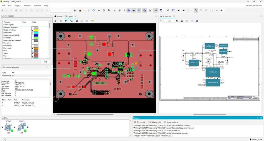
Visualize test coverage and customer specific attributes in schematic, layout and netlist navigation views. This New-Generation Viewer also provides unique digitization feature that creates schematic view from PDF. - twDocumentor for shop floor documentation
A powerful document management tool that allows quick and easy creation of comprehensive shop floor documentation, as well as the formatting of testability analysis reports. - Advanced reporting
Produce comprehensive reports in a variety of formats that highlight predicted production yield, test coverage by component type, predict placement time, etc. - Cost modeling
Predict test execution times, total engineering time and calculate hardware costs such as; test fixture, power supply, spring probes, wiring and vector-less sensors etc.
Electrical Rules Checking
Electrical rules checking (eDfT) enables the identification and rectification of electrical rules violations before finalizing the board layout, in order to prevent costly design re-spins.
These rules are distributed into 3 categories: Design rules, Testability rules, Boundary-scan rules. These rules are derived from formal standards and include rules commonly applied throughout the electronics industry.
Specific customer requirements can be specified in a low-code language using the custom rules feature.
Place the probes
Probes are placed by considering the mechanical (mDfT) and design-for-test (DfT) constraints practiced by respective companies.
Once the possible probe positions have been analyzed, the nail allocation algorithm selects the best of these opportunities for the nail positioning according to the preferences set by the user.
This allows the estimated coverage to be calculated according to the achievable test access.
Select manufacturing strategy
When deciding on the optimal test flow, it is important to consider all available test and inspection machines such as AOI, X-Ray, BST, ICT, FPT and Functional test.
The “test line” is easily defined using a simple drag and drop operation.
The theoretical test models, for coverage estimation and the actual test models, for coverage measurement, can be combined to reflect your manufacturing strategy.
Test coverage estimation
Each of the theoretical test strategies allows selection of tester settings, from a feature list for a particular test strategy.
In order to provide a more accurate estimation, any specific test features that are available on the target tester should be included in the analysis. This aligns the estimated coverage to the real tester coverage.
TestWay Express handles cross optimization along the test line, such as Boundary-Scan or AOI, that can be used to minimize the In-Circuit Test or Flying Probe Test.
Design to build, Design to test
The test strategies simulation results are used to automate the program generation for SPI, Pick-&-Place, Chip shooter, AOI, X-Ray, Boundary-scan, Flying Probe, and In-circuit Test.
Output processors are available for all brands of production, inspection and test equipment.
Test for Excellence: Check real coverage
The real test coverage is determined after the test has been developed and debugged, by analyzing the test program or coverage reports, from any test and inspection systems.
By analyzing the true coverage, test coverage analysis reports can be created to reflect what is actually being tested.
The coverage analysis is based on industry standard metrics such as:
By obtaining a reference point from early coverage estimation and comparing this with the coverage provided by the real test program, it is possible to identify deviations in order to drive continuous improvements.
