Search

PS200S

PS200S Thermal Warpage and Strain Measurement Tool

Using the same Shadow Moiré technology as the AXP 2.0, the PS200S  is a laboratory based solution for products up to 150 mm x 200 mm. The PS200S uses the same software suite as the AXP 2.0, and will measure surface strain and coefficients of thermal expansion from room temperature upwards.

Quick Enquiry

If you want to know more about PS200S

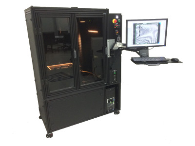
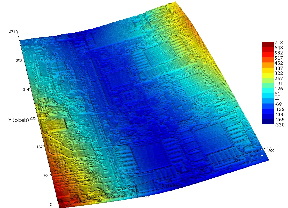
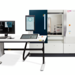
The TherMoiré® PS200S is a metrology solution that utilizes the Shadow Moiré measurement technique combined with automated phase-stepping to characterize out-of-plane displacement for samples up to 150 mm x 200 mm. With time-temperature profiling capability, the TherMoiré® PS200S captures a complete history of a sample’s behaviour during a user-defined thermal excursion.

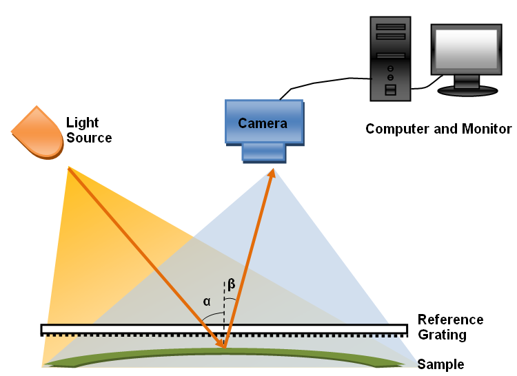
The combination of the Shadow Moiré technique and dynamic temperature profiling is the foundation of the patented TherMoiré® platform. Dynamic profiling is the most effective approach to analyse mechanical behaviour induced by real-world processes and operating environments. Using the TherMoiré® PS200S, engineers will gain a better understanding of the interactions of materials, packages, substrates and complete assemblies, allowing for a thorough analysis of the system and improving its reliability and first pass yield performance. The PS200S is critical to helping meet the ever increasing interconnect and reliability requirements on both the device and substrate levels.

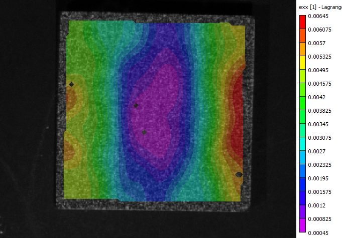
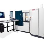
The PS200S is a laboratory solution designed for use in R&D, production and failure analysis/reliability applications, and accepts the Digital Image Correlation module for Strain and coefficient of thermal expansion assessment.

  • Failure/defect analysis
  • Quality assurance/quality control
  • High Volume Testing complimented by Part Tracking technology
  • Pass/Fail decisions versus industry standards, streamlined by Real Time Analysis software
  • Shape matching between attaching interfaces via Interface Analysis Software
  • Material and Design Choices
  • FEA Model Validation
  • Optional Digital Image Correlation (DIC) 2.0 Module
Digital Fringe Projection

Flatness Measurement and Analysis Technique

The Digital Fringe Projection (DFP) technique compliments the shadow moiré technique by adding step height measurement capabilities at high data point density. This technique is particularly useful for measurement of connectors, sockets, assembled modules, and PCB local areas.

No grating is needed for the DFP technique, which helps with issues like outgassing and temperature uniformity sometimes seen with the shadow moiré technique. DFP also has the advantage of not being limited by data density, unlike the shadow moiré technique.

DFP has the disadvantage of warpage resolution being dependent on field of view. For this technique a field of view of 64x48mm, generating a measurement resolution of 5 microns, was chosen.

The strengths of the DFP measurement technique include:

  • Full field data acquired in less than 2 seconds
  • Able to measure sudden and large height changes up to nearly 20mm
  • High data point density

The DFP technique is offered as:

  • A DFP module on the AXP system
  • The base technology for the CXP system


Digital Image Correlation

In-plane strain and CTE measurement Technique

Digital Image Correlation (DIC) is a non-contact, full-field optical technique for measuring both in-plane and out-of-plane displacements of an object surface. A high contrast, random speckle pattern is applied to the surface of interest. Two cameras are mounted above the oven, viewing the sample from different angles.

Two simultaneous images from both cameras are digitized. Software identifies the same point on the surface from both perspectives, using pattern recognition of the speckles within a small pixel window. Using the principle of stereo triangulation, the spatial position of the pixel window relative to the cameras is determined in 3D space. Stepping the pixel window across the sample, the displacement of the surface can be mapped out in 3 axes.

The strengths of the DIC measurement technique include:

  • In-plane strain measurement at <150 microstrain
  • Calculate average surface CTE from strain and temperature data

The DIC technique is offered in the form of the DIC 2.0 module on the following Akrometrix tools:

  • AXP
  • PS200S


Shadow Moiré

Flatness Measurement and Analysis Technique

Shadow Moiré is a non-contact, full-field optical technique that uses geometric interference between a reference grating and its shadow on a sample to measure relative vertical displacement at each pixel position in the resulting image. It requires a Ronchi-ruled grating, a white line light source at approximately 45 degrees to the grating and a camera perpendicular to the grating. Its optical configuration is shown in the figure to the right. A technique, known as phase stepping, is applied to shadow moiré to increase measurement resolution and provide automatic ordering of the interference fringes. This technique is implemented by vertically translating the sample relative to the grating

The strengths of the shadow moiré measurement technique include:

  • Full field data acquired in less than 2 seconds
  • Resolution down to <1 micron
  • Resolution is unchanged by field of view
  • Highly robust with minimal moving parts

The shadow moiré technique is offered on the following Akrometrix tools:

  • AXP
  • PS200S
  • PS600S
  • AKM600P


Akrometrix Studio is an advanced set of integrated software modules that work together to run all Akrometrix equipment. The Studio software suite takes users from profile creation, through warpage measurement, temperature profiling, analysis of warpage data, and reporting seamlessly. Studio software users will have nearly the same experience in working with different Akrometrix measurement technologies and different Akrometrix measurement tools.

The Studio Suite is broken up into a series of programs that work together

Profile Generator: (Create temperature profiles)
  • Create thermal profiles graphically; ‘click’ to add temperature points and actions
  • Assign ramp rates, soak times and cool down periods using numerical settings
  • Set machine control action points by clicking on profile segments
    • Measurement points (capturing phase images)
    • Blower on/off points
    • Exhaust on/off points

Surface Measurement: (Measurement Setup)
  • Work from a live system view to setup multiple test parameters
  • Run multiple phase image and 3D measurement results windows concurrently
  • View displacement graphs and data when data is acquired
  • Work with multiple regions of interest
  • DIC, DFP, CRE6, and CM modules integrate seamlessly into the same workflow
  • Includes Part Tracking feature and option for Real Time Analysis (RTA) software

Thermal Profiler: (Measure warpage over temperature)
  • Uses test setup from Surface Measurement to apply over temperature
  • Load profiles from Profile Generator
  • Optimize thermal conditions: heater power, lower while heating
  • Immediate results feedback during profiling

Surface Analysis: (In-depth data processing)
  • Analyse and compare 2D and 3D data sets
    • View up to 2 million displacement data points on each graph
    • Control multiple graphs on-screen at once
    • Mask areas and burn masks permanently into phase images
    • Calculate one displacement data set relative to another
    • Export data for further analysis into computational applications such as ANSYS and MATLAB
    • Draw 2D chord lines across phase images at any angle
    • Zoom, rotate, crop and export 3D displacement graphs in multiple format

    Batch Processing

    • apply masks, filters, chords, rotation and other operations to hundreds of phase data sets, provide multiple output and export options for graphical and analytical analyses, and export data for use in Interface Analysis

Interface Analysis: Understanding Warpage Between Two Mating Surfaces

Surface-mount components warp during the reflow process, and the area where they attach also changes shape during assembly. This interface between components is where solder, paste, and gaps created due to thermal expansion combine to create 100% good products, or defects such as Head-in-Pillow, Shorts, and Opens. Fully understanding that critical interface between surfaces is more important than ever.

While standard Akrometrix software allowed the analysis of an individual surface, such as a PCB or BGA, Interface Analysis is new software that enables 3D, 2D, and statistical review of a complete interface. Users can now visualize and quantify exactly how two surfaces will mate together. By combining this feature with the ability to measure surfaces at each temperature point during reflow, solder joint formation or failure can be predicted much more easily.

Interface Analysis works with data supplied by any of the 250+ TherMoiré systems in use throughout the worldwide Electronics supply chain today. Introducing unique features such as Pass/Warning/Fail maps, and various gap and surface gauge information, Interface Analysis lets users see what is happening between two dynamic surfaces through the reflow process. Applications include SMT Assembly Planning and Troubleshooting, Failure Analysis, Supplier Qualification and Comparison, Ongoing SPC, Package Design, and FEA Modelling Validation.

Two Important application areas are Package-on-Package Design and Assembly and Package-to-PCB Design and Assembly

Real Time Analysis for Pass/Warning/Fail Decisions

Real Time Analysis (RTA) takes user input warning and failure gauge limits and gives immediate feedback on the region or regions that fall within desires performance. It is based on an easy to use recipe approach for up front processing and RTA is designed to scale to high volume applications, taking the analysis steps out of warpage measurements and going straight to decisions. It scales to hundreds of regions measured in only 2 seconds, gives tabular and visual output to users immediately after measurement.

Part Tracking

Part Tracking technology is a software application included in Akrometrix Surface Measurement that increases system throughput while reducing user to user and system to system measurement variation.  It automatically locates, crops, and rotates measured samples. Part Tracking uses edge recognition technology to locate a part in space and automatically crop/rotate the sample for processing of the found surface area. It increases system throughput by reducing setup time, improves run to run repeatability, and improves system to system and user to user reproducibility. It has all the Shadow Moire tools as standard.

Akrometrix General Brochure