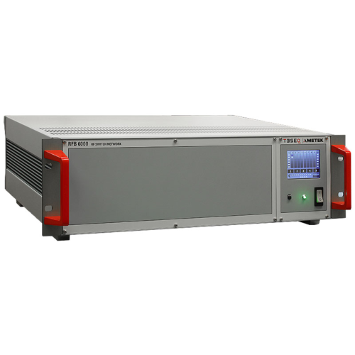
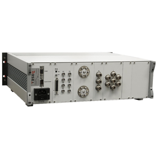
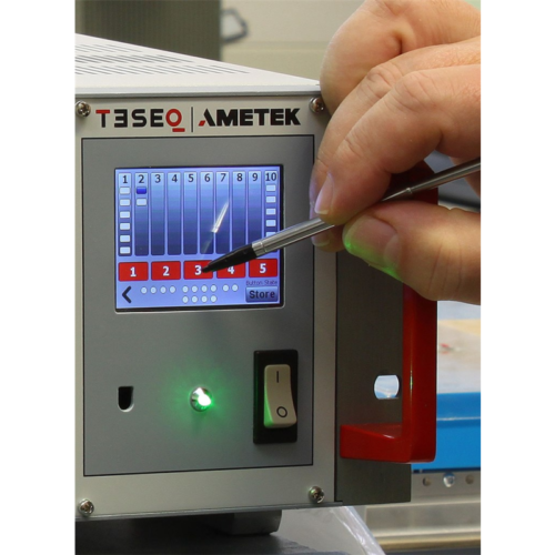
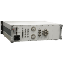
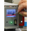
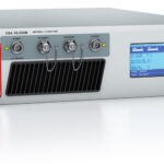
The RF switch network can be configured to switch RF signals in a wide range of automatic test systems. Various switch configurations are available, connecting one input to either two or six outputs. The 3HU main frame consists of a power supply and remote interface and can accept any combination of plug-in modules up to the maximum dimension of the main frame. In addition up to 8 power meters can be connected to measure the forward power close to the antenna, e.g. in a separate amplifier room. A control signal port (User port) allows switching of amplifiers and other functions. Each switch as well as the additional functions can be individually controlled through the front panel touch screen, e.g. for installation and maintenance purpose. An USB to serial / optical converter with 20 m optical cable allows always a safe and secure remote control of the device, also in a noisy and electromagnetically disturbed environment. All RF switches are high quality with an operating lifetime of at least one million operations. While able to pass high power levels, they are designed to switch only during absence of RF power.
| Parameter | Value |
|---|---|
| Power supply | 100 – 240 V AC / 47 – 63 Hz |
| Display | 3″ TFT with touch, 320×240 pix. |
| Remote control RS485 | Connector D-Sub 9 pole, up to 9600 Bd (for RF switches only) |
| Remote control RS232 optical | Connector 2 x HFBRx523 socket for 1 mm fiber optic cable with standard length of 20 m, for other distances on request
115200 Bd, 8, N, 1 |
| RF Impedance of the switches | 50 Ω |
| RF Isolation between the ports | ≥55 dB |
| Switch life time | 1M switch cycles (absence of RF power during switching required) |
